Building a Flatfield Mask

The use of bias, dark and flat frames to calibrate light frames is fundamental for astrophotography. While bias and dark frames can be created with relatively little effort, a more complicated setup is required to create flat frames. Flat frames require a mask that is as evenly illuminated as possible in order to be able to correct differences in brightness in the light frames. These flatfield masks can be purchased from specialist astronomy dealers for several hundred euros. For larger aperture diameters, the price can easily reach into the mid to high three-digit range. In my case, I would need a flatfield mask with a diameter of around 240 mm. These would cost around 500 € from specialist dealers. If you want to spend less money on a mask, you can also build one yourself. In this blog post, I would like to show you how I built the flatfield mask for my Bresser NT203/1000.
Parts list
The following materials are required for the project:
| Component | Notes | Price |
|---|---|---|
| Round acrylic sheet | see one of the many acrylic cutting websites; should be as thick as the LED strip is wide | 13.65 € |
| LED strip | sufficient length for one circumference of the acrylic glass panel; preferably cold light (6000 K); highest possible LED density | 6.99 € |
| Bidirectional filament adhesive tape | 11.99 € | |
| Frosted glass film | without textured surface | 7.99 € |
| White lacquer film or other white reflective surfaces | 5.45 € | |
| Acrylic glass-compatible adhesive | 9.99 € | |
| Black adhesive tape | e.g. insulating adhesive tape | 1.25 € |
| Total | 57.31 € |
A 3D printer is also required to produce the mounting. The costs I paid for the materials can be seen next to the individual components. It is possible to buy these components even cheaper with a little more research.
Preparation of the light guide plate
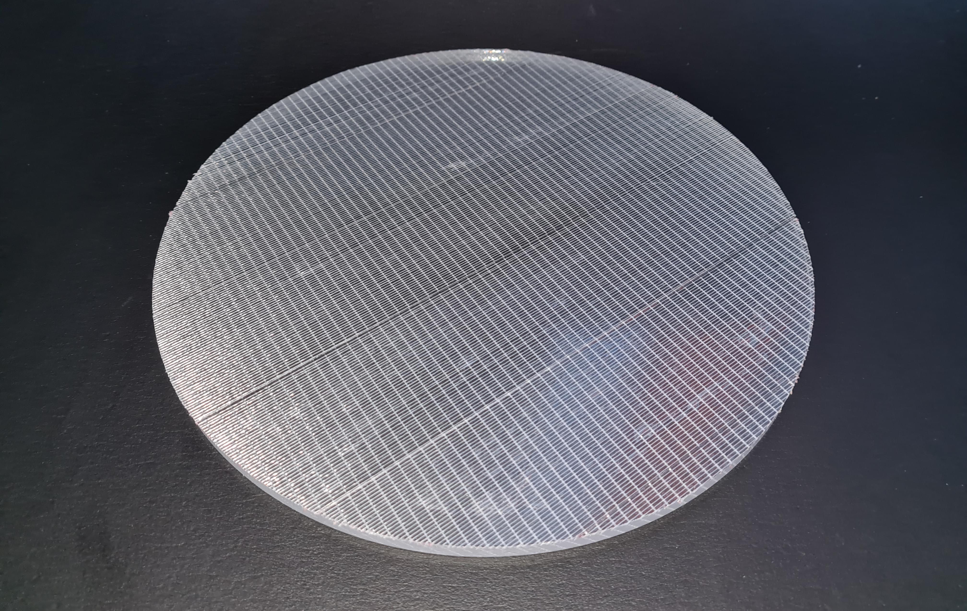
Instead of an LED matrix, which creates an evenly illuminated surface through a diffuser, a design with a light guide plate was chosen for this flatfield mask. The light guide plate is illuminated by the LED strip attached to the side and distributes the light over the entire surface. Professional light guide plates, which have an engraved surface to diffuse the light, can quickly become very expensive given the required surface area and thickness. These would then offer no budgetary advantage over a very large LED matrix. Instead, a simple acrylic glass panel should be used. The first step is to remove all protective film from the acrylic sheet. The bidirectional filament adhesive tape is then applied to one side, which will later become the light-emitting side. Care should be taken to ensure that the individual adhesive strips do not overlap and all run in the same direction. The protruding ends can be trimmed with a knife. During the entire process, care should be taken not to scratch the acrylic glass panel.

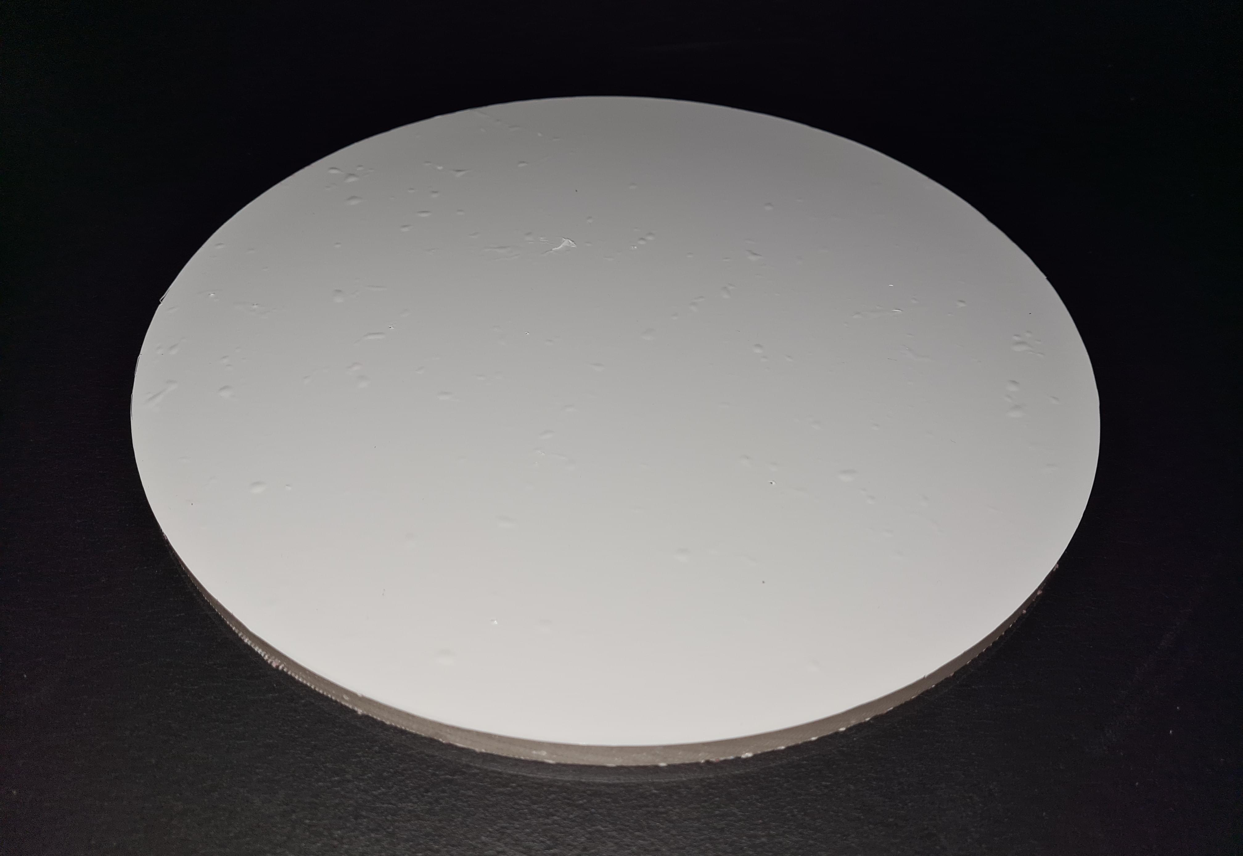
In the next step, the white paint film is applied to the opposite side. If this is not self-adhesive, additional adhesive must be used here. The adhesive should be applied as evenly as possible. Air bubbles could not be avoided. In the end, several layers were used to block all light.

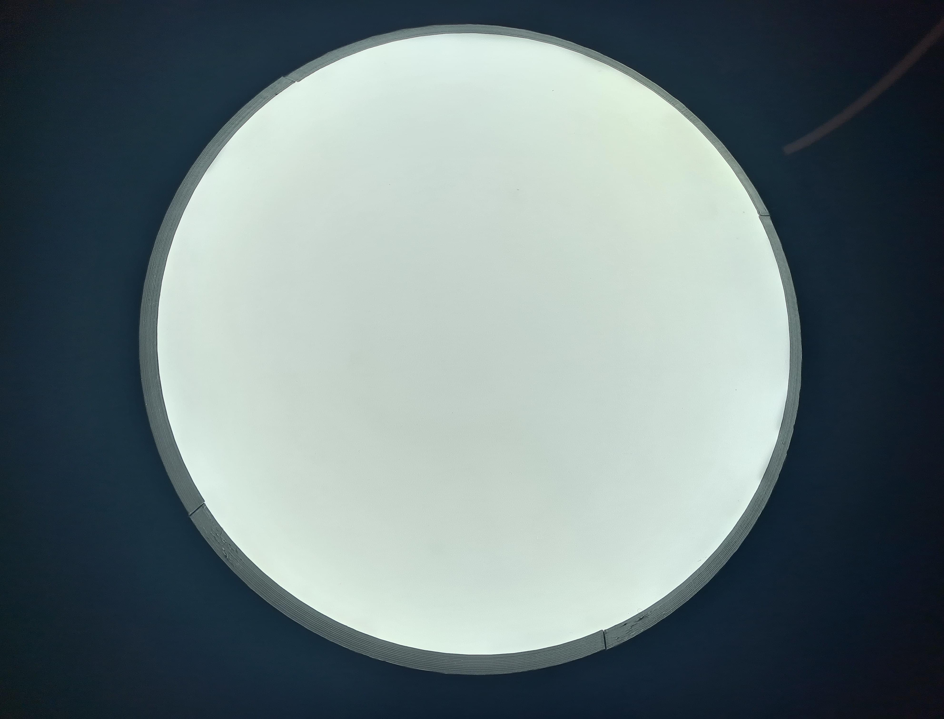
The LED strip can then be glued on. First, however, the required length should be determined by placing the strip against the circumference of the circle. The LED segments that are not required can be cut off. The adhesive must then be applied to the side with the LED diodes. It is advisable to think beforehand about how the LED strip will be pressed against the edge of the panel during drying. Once drying is complete, a first attempt at lighting can be made. The light pattern inside the glass should already be as uniform as possible. The stray light escaping from the side can still be ignored. If the result is not satisfactory, it must be improved. This may be due to insufficient contact between the LED strip and the edge. In this case, new gluing must be carried out if possible. If the result is satisfactory, the edges of the panel, including the LED strips, can be covered with black adhesive tape. Care should be taken to ensure that as little illuminated area as possible is covered. My acrylic glass plate was ordered with enough spare area so that the black adhesive strips are not visible in the telescope’s field of view.
I originally planned to tape the frosted glass film on the filament tape. However, the frosted film was not able to fully obscure the flament pattern. In the final design multiple circular cutouts of frosted film were used. The sheets were stacked and placed in the mounting backet and pressed down by the lighting setup.
Manufacturing the mounting
To make it as easy as possible to use, the illumination system should be inserted into the telescope tube in the same way as the cover supplied with the telescope. One problem here is the production. Since only a Prusa MINI+ with 180 mm x 180 mm x 180 mm build room is available, the entire mount cannot be printed as a single part. A precisely fitting mounting is also very difficult to realize. Numerous tolerances in the radial and axial direction result in significant tolerance stacks. These must be compensated for in the design.
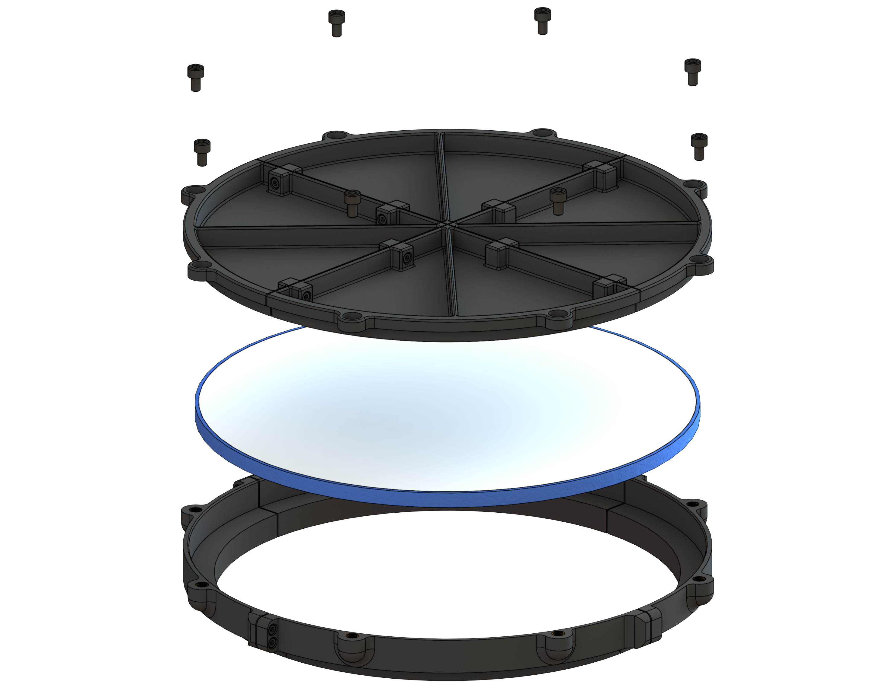
The final design provides for a mounting ring which is placed on the tube like the supplied cover. The illumination system, together with the light diffusion sheets is inserted into this ring. A lid is used to press the illumination system into the mounting ring. One of the mouning ring segments has a hole for the power cable. The setup is shown in the following image:

The parts are printed using PETG and threaded inserts are used to join the parts together.
Final thoughts
The self-build flatfield mask creates an (almost) evenly illuminated surface. At least with the bare eye, no variation in brightness is visible. With a camera, a slight reduction of brightness towards the middle of the mask is visible. If this effect is still visible in the telescopes field of view is yet to be determined.

There are multiple options to improve the light guiding plate design. The filament tape works fine on the light-emitting side of the light guide plate. Placeing another filament tape film on the other (reflective) side oth the light guide plate might improve the light scattering effect in the guide plate. The white adhesive film worked great. Greater care should be taken, when placeing the film, to not create air bubbles. The light diffusion system needs improvement. The forsted film worked good enough in the end. Maybe a professional light diffusion plate is a better option here. Another option is to use a translucent white acrylic plate instead of a fully transparent one. The LED strip with USB Type A connector works great. Same goes for the monting mechanism. Using a little bit of adhesive foam tape to compensate for tolerances also works great. Quite a bit of trial and error was needed to create this flatmask. A sign of this approach is the adhesive residue from previous tries on the acrylic glass. If this residue has any effect on the quality of the flatmask needs to be examined. As of writing this, a test run with the telescope is still pending.